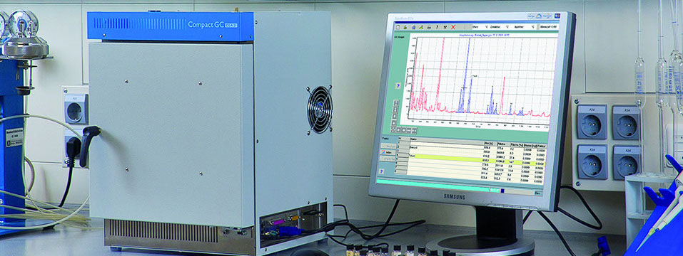
Gas Chromatographs for Education and Industry
Technique of gas chromatography
The following section describes the individual components of a gas chromatograph, their technical design, and provides notes on their practical operation:
"If the column is described as the heart of chromatography, then sample introduction may, with some justification, be referred to as the Achilles heel"
V. Pretorius and W.Bertsch, HRC & CC, 6/1983, 64
This quote illustrates the fact that a patented solution for sample introduction in gas chromatography is still not available. Technically, it is not easy to introduce a small amount of liquid having a volume of 0.1-1 microlitres precisely and reproducibly into a system at excess pressure. Consequently, there are a large number of designs and techniques of sample introduction; the two most familiar are described as follows.
1. Injector without split
This type of sample introduction is based on a simple principle. A microlitre syringe is used to puncture the septum, a rubber-like membrane; the needle is inserted fully and the plunger is pressed down to inject a measured amount of liquid into the vaporisation chamber of the injector, whose temperature should be several tens of degrees higher than the boiling point of the mixture.
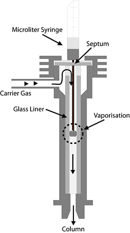
The vaporisation chamber usually consists of a glass tube, or liner, with an internal diameter of 2-5 millimetres. An obstruction is usually positioned in the middle of the liner to intercept the drop of liquid ejected from the syringe. On this obstruction, the drop must then be vaporised fully and rapidly, if possible, into a small gas cloud. This procedure is also termed flash vaporisation. The gas cloud is then transported by a flow of carrier gas into the column, where the actual separation takes place.
This type of sample introduction has the following basic disadvantages:
• The drop of liquid is not vaporised instantaneously but over a certain time period. During this period, the flow of carrier gas disperses the gas cloud.
• The expulsion of the gas cloud from the injector into the column is a process comparable with a dilution series. The concentration profile of an injected sample at the outlet of the injector exhibits the typical, exponential characteristic of such processes over the last part. In principle, this applies to all sample introduction systems but is particularly evident in the case of this simple construction.
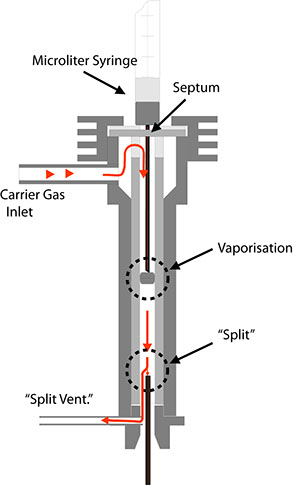
2. Injector with split
This design allows the flow of carrier gas to be split after introduction of the sample. In this case, the flow of gas through the injector is much larger than through the separation column. Fig. 23 is meant to demonstrate this. First, the injected sample is vaporised. The gas cloud is transported by the carrier gas to the split, where the gas flow is separated. The smaller portion flows into the column (usually consisting of a capillary column), while the larger portion escapes through the line leading to the split valve. The ratio of the gas flow through the column and the escaping gas flow is termed the split ratio. This value typically lies between 1:10 and 1:100. Two results are achieved by this process:
Due to the relatively high speed at which the gas cloud flows past the split point in the injector, the concentration-time characteristic of the test substances is much narrower, i.e. the tailing at the peak end is greatly reduced by the expulsion process.
The absolute quantity of the test substance reaching the column is reduced by the same factor as the split ratio. This is a necessity for capillary columns, as their capacity for carrying substances requiring separation is several degrees of magnitude lower than that of packed columns. The following sample calculation is meant to elucidate this: Assume that a carrier gas flows through the column at a rate of 10 ml/min. and that the flow rate through the split outlet is 90 ml/min. When the gas cloud flows past the split point at a rate of 100 ml/min., only 10% of the injected sample will reach the column.
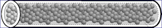
1. Packed columns
This type of column consists of a chromium-steel or glass tube containing a porous material with a particle diameter of 0.05 to 0.5 mm which acts as the carrier and is coated with the stationary, liquid phase. The large surface area of this substance allows rapid attainment of the diffusion equilibrium between the mobile gaseous phase and the stationary liquid phase. Depending on the application involved, the proportion by mass of the liquid phases lies between 0.5 and 25%.
Packed columns contain much more liquid phase than capillary columns and are thus very suitable for separating highly volatile components as well as large sample quantities, particularly in conjunction with a thermal conductivity detector (TCD). Due to its design, the TCD is less sensitive than other detectors, such as the flame ionisation detector (FID). Standard version 1 of the device used here comprises a chromium-steel packed column with an internal diameter of 2 mm and a length of 2 m. Its carrier material consists of a preparation of diatomite with a grain size of 80-100 mesh and a coating of 5 % polydimethylsiloxane (OV-1).
2. Capillary columns
Nowadays, these columns usually consist of a thinwalled tube made of pure quartz SiO2, or fused silica. Columns like this are also termed open tubular columns (OTC). Here, the stationary phase consists of a thin film applied to the inside of the tube wall. Often, this film is also fixed to the silicon dioxide by means of chemical bonds. This allows the columns to be washed using suitable solvents without loosening the lining. For mechanical protection, the columns are usually equipped with a plastic coating of polyimide. Capillary columns are commercially available in graduated internal and external diameters:
Internal • External
0.10mm 0.27mm
0.20mm 0.35mm
0.25mm 0.38mm
0.32mm 0.48mm
0.53mm 0.75mm
The film thickness of the stationary phase varies between 0.1 and 5 micrometers. The columns have a standard length of between 10 and 50 meters. The above-mentioned distribution characteristics only apply approximately to low concentrations. If a column is overloaded in an attempt to separate large quantities of substances, distorted peaks occur, thus impairing the separation efficiency. It is clearly evident that columns with a thicker stationary phase can handle larger quantities of substances for the purpose of analysis. On the other hand, the diffusion processes forming the basis of separation are generally faster and more extensive if small dimensions are involved, i.e. thin columns with small film thicknesses for the stationary phase provide higher separation efficiency.
A compromise needs to be struck between these two conflicting requirements. This compromise is closely related to the detector used, as the substances emerging from the column need to generate an electrical signal in the detector. In any measurement circuit however, a detector always has the fundamental property of generating an interference signal which is termed noise. Just like weak signals from broadcasting stations easily fade on the radio, a very small peak is easily drowned by the inherent noise in the detector circuit. Put differently: Sensitive detectors like the flame ionisation detector allow the use of low-capacity columns which have a high separation efficiency, whereas a thermal conductivity detector, for example, requires the use of high-capacity columns due to its much lower sensitivity. Version 2 of the CGA devices, for example, uses a micro TCD in conjunction with a capillary column with an internal diameter of 0.53 mm and a film thickness of 5 micrometers.
Detectors
1. Thermal conductivity detector (TCD)
The detector of a chromatograph is meant to output an electronic signal when a component of the substance to be analysed emerges from the column. There are diverse methods of generating such electrical signals, one of them being the thermal conductivity detector described in the following.
The ability of gases to conduct heat depends directly on the mass of their molecules. According to the kinetic theory of gases, light molecules are better conductors of heat than heavy ones. This fact is made use of by the TCD. Drawing below shows its fundamental design.
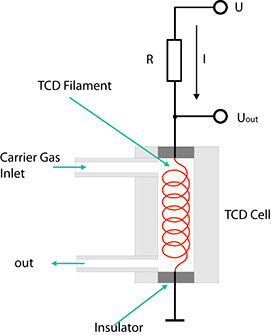
The carrier gas from the separation column flows through a cylindrical chamber containing a thin wire made of a tungsten alloy. This wire, or filament, has an electrical resistance R which depends on the temperature of the filament. In the case of metals, this resistance generally increases with the temperature. Such conductors are said to have a positive temperature coefficient (PTC). If a current I flows through the resistance, the voltage VDet through it is determined using Ohm's law:
VDet = R(T) • I
If a component with a higher molecular mass than that of the carrier gas emerges from the column, the heat from the heating filament is channelled off more slowly by the gas mixture. Consequently, the temperature T of the filament rises, and so does its electrical resistance. Given a constant current I, UDet also rises as a result. This configuration hence indicates changes in the composition of a carrier gas in the form of voltage variations.
However, one disadvantage of this simple detector is that any other extraneous factor influencing the temperature of the filament also influences the voltage UDet and is thus superimposed on the effective signal. Examples of such undesirable effects are:
• Change in the flow of gas
• Variations in the operating voltage
• Change in the ambient temperature
In practice therefore, the detector is not used in the form described above. The configuration shown below proves much more practical. In this case, the carrier gas flows through a second measurement cell before entering the injector.
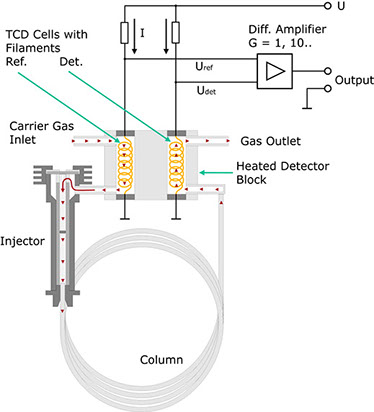
Both measurement cells are located together in a metal block possessing a high thermal conductivity. Here too, the current I results in a voltage drop URef across the heating filament. In the absence of a test substance, UDet should be equal to URef if both the tungsten wires are identical and thus have the same resistance. The bridge voltage UDet-URef should be zero. This no longer applies on the emergence of a component from the column. Now a difference arises between UDet and URef. In a first approximation, this difference is proportional to the concentration of the expelled component. The voltage is amplified and recorded as a function of time.
Why is this detector much less sensitive to changes in the variables mentioned above? For example, let us assume that the ambient temperature rises. As the filaments are thermally coupled, this rise affects both of them in equal measure. Consequently, UDet and URef rise, the difference between these two values ideally remaining constant. Ideally speaking, changes in the flow of the carrier gas do not affect the bridge voltage either, as such changes influence the temperature of both filaments, i.e. UDet and URef change accordingly but the difference between them remains nearly constant.
Summary of the essential properties of a TCD:
• At low concentrations of foreign substances, the output signal is proportional to the concentration.
• The sensitivity of a TCD depends on the substances involved.
• The dimensions of the measurement cell of a TCD must remain above a certain limit. The minimum diameter of such cells is approx. 2 mm; the volume is relatively large for gas flows in standard capillary columns. A TCD can only be used successfully in conjunction with capillary columns if these columns have a sufficient width (e.g. 0.53 mm internal diameter) and high film thickness (e.g. 5 micrometers).
• TCDs are non-destructive, i.e. the eluted substances are not changed.
• TCDs are not particularly suitable for trace analysis.
• TCDs should only be used with carrier gases possessing a high thermal conductivity. Hydrogen and helium are suitable for this purpose.
• If the temperature of the column furnace has been programmed, the reference line can be expected to drift.
• In the hot state, the tungsten filaments of the TCD might be adversely affected through oxidation by oxygen in the carrier gas. This can happen, for example, if the flow of carrier gas has inadvertently not been turned on. On no account must the TCD be operated with air for extended periods!
2. Flame ionisation detector (FID)
The flame ionisation detector used in your device (if you have a CGA 3) is much more efficient than the thermal conductivity detector described previously. Its operation is described in this chapter.
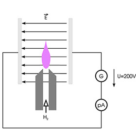
If a hydrogen flame is placed between the plates of a charged capacitor as shown above, a low electrical current of a few hundred femtoamperes flows through the circuit. It is assumed that thermal ionisation gives rise to free electrons and ions, although the yield of charged particles is very low. However, if the flow of hydrogen in such a configuration includes substances containing C-H bonds, e.g. alkanes, the current rises sharply. This is attributed to the formation of CHO+ ions and free electrons from CH• radicals. However, the yield of ions is very low in this case too. On average, only a handful of charge carriers are obtained from 500 000 atoms of carbon; nevertheless, this effect can be used successfully to detect hydrocarbons and related compounds. The schematic diagram below shows the technical design of the FID.
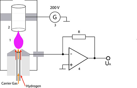
The gas mixture to be analysed emerges from the capillary column right below a metallic nozzle (1). From there, it is transported by the hydrogen flow to the flame. Purified air is fed to this flame via separate channels. A circular electrode (2) is located above the flame; this electrode together with the nozzle, the voltage source (3) and the current-voltage converter (4) forms a closed electrical circuit. This detector must be heated to prevent condensation of the substances eluted from the column and of the H20 produced in this process.
Summary of the essential properties of an FID:
• The most widely used type of detector with a simple, robust design
• Only detects substances containing C-H bonds
• Requires hydrogen and purified air (free of hydrocarbons) for operation
• Needs to be ignited
• High sensitivity and measurement response (ratio of the smallest to the largest effective signal)
• Sensitivity depends on the type of the substances detected
• Relatively insensitive to fluctuations in temperature and gas flow
Home
Contact us
Legal Notice